Kaypro 2X
TODO: Overview photo
Computers in Collection
General Info
Mechanical
| Label | Part | Qty | Description | Replacement |
| A | Top cover top screw | 2 | black oxide 18-8 stainless steel Phillips flat head screw, 82 degree countersink, 6-32 thread, 5/16” long | McMaster-Carr 96640A113 |
| B | Top cover side screw | 8 | black oxide 18-8 stainless steel Phillips extra-wide truss head screw, 6-32 thread, 5/16” long | McMaster-Carr 94779A420 |
| B | Keyboard pivot strip screw | 3 | black oxide 18-8 stainless steel Phillips extra-wide truss head screw, 6-32 thread, 5/16” long | McMaster-Carr 94779A420 |
| B | Rear panel random screw | 2 | black oxide 18-8 stainless steel Phillips extra-wide truss head screw, 6-32 thread, 5/16” long | McMaster-Carr 94779A420 |
| C | Logic board mounting screw | 2 | black oxide 18-8 stainless steel Phillips pan head screw, 6-32 thread, 1/2” long | McMaster-Carr 91249A148 |
| D | Parallel port connector-case screw | 2 | black oxide 18-8 stainless steel Phillips pan head screw, 4-40 thread, 3/8” long | McMaster-Carr 91249A108 |
| E | Serial data connector-case screw | 2 | male-female threaded jack screw, 5/16” long male thread | McMaster-Carr 92710A217 |
| E | Serial printer connector-case screw | 2 | male-female threaded jack screw, 5/16” long male thread | McMaster-Carr 92710A217 |
| F | Rear panel case screw | 3 | black-oxide 18-8 stainless steel Phillips extra-wide truss head screw, 6-32 thread, 3/8” long | McMaster-Carr 94779A430 |
Memory Map
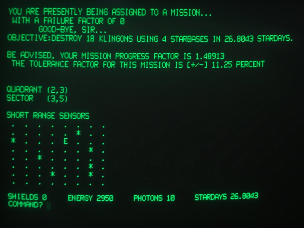
I wanted to get the Citadel BBS software running on this Kaypro, so had to do a bit of reverse-engineering to write the necessary modem driver code.
Using “Kaypro 84 schematic” by Micro Cornucopia, which hopefully is reflective of the hardware I have…
Zilog Z8440A U17 SIO-2 is connected to the TMS99532 modem chip’s RCVD, XMTD, DCD#, etc. A0 is connected to the B/A# pin on the SIO, and A1 is connected to the C/D# pin.
IO memory addressing
| A7 | A5 | A4:A2 | A1 | A0 | ADDR | Select | Related Peripherals |
| 0 | 0 | 000 | 00-03 | BAUDA | Serial Data I/O (baud) | ||
| 0 | 0 | 001 | 0 | 0 | 04 | SIOCE1.A.DAT | Serial Data I/O (serial), keyboard |
| 0 | 0 | 001 | 0 | 1 | 05 | SIOCE1.B.DAT | Serial Data I/O (serial), keyboard |
| 0 | 0 | 001 | 1 | 0 | 06 | SIOCE1.A.CMD | Serial Data I/O (serial), keyboard |
| 0 | 0 | 001 | 1 | 1 | 07 | SIOCE1.B.CMD | Serial Data I/O (serial), keyboard |
| 0 | 0 | 010 | 08-0B | BAUDB | Serial Printer I/O (baud) | ||
| 0 | 0 | 011 | 0 | 0 | 0C | SIOCE2.A.DAT | Serial Printer I/O (serial), internal modem |
| 0 | 0 | 011 | 0 | 1 | 0D | SIOCE2.B.DAT | Serial Printer I/O (serial), internal modem |
| 0 | 0 | 011 | 1 | 0 | 0E | SIOCE2.A.CMD | Serial Printer I/O (serial), internal modem |
| 0 | 0 | 011 | 1 | 1 | 0F | SIOCE2.B.CMD | Serial Printer I/O (serial), internal modem |
| 0 | 0 | 100 | 10-13 | FDSKCS | |||
| 0 | 0 | 101 | 14-17 | SYSPRT | Floppy, character set, RAM/ROM switch, printer | ||
| 0 | 0 | 110 | 18-1B | PDATA | Parallel Printer | ||
| 0 | 0 | 111 | 1C-1F | VIDCS | Video | ||
| 0 | 1 | 000 | 0 | 0 | 20 | PIOCS.A.DAT | RTC, internal modem |
| 0 | 1 | 000 | 0 | 1 | 21 | PIOCS.B.DAT | RTC, internal modem |
| 0 | 1 | 000 | 1 | 0 | 22 | PIOCS.A.CMD | RTC, internal modem |
| 0 | 1 | 000 | 1 | 1 | 23 | PIOCS.B.CMD | RTC, internal modem |
| 0 | 1 | 001 | 24-27 | RTCS | RTC |
Data Carrier Detect is read by selecting SIO-2 register 0 and reading. Bit 3 (0x08) will be 1 if carrier is detected.
Off-hook is performed by PIO port B, pin 6 (and a NAND with the tone dialer IC?).
Kaypro 2X MTC, serial 274518
Inventory
Acquired from OMSI “Craig” donation in August of 2019.
Contains onboard 300 baud modem. “KAYPRO 2X” printed between the floppy drive bays, and on the back below the handle strap.
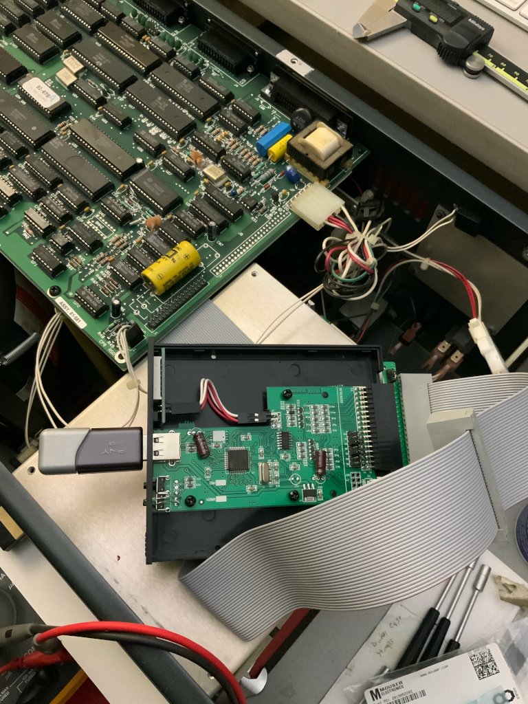
Logic Board
- “ASSY. 81-581”
- “SER NO. 74396”
- “KVO MADE IN U.S.A.”
- ROM is “81-478-A”, with “A” stamped in blue ink.
- Latest IC date codes are late-1984.
- “KAYPRO 83-194 / 1494 8343 7505-4” custom IC U29.
- “3A-2018 81-189 / 1470 8348” custom IC U10.
- “MOSTEK(C)8418 MK3880N-4 Z80-CPU” Z-80 processor U43.
- Texas Instruments TMS99531/2 FSK modem chip set – Bell 103 compatible?
- National Semiconductor MM58167AN real-time clock.

System is 4MHz, uses custom ICs.
The “81-478-A” ROM version is portrayed as “Kaypro 10 Monitor “U” ROM v2.01”. Found a dump of the ROM online and sure enough, it contains “Kaypro Corporation Version 2.01”, the same message on-screen at boot time.
Another source backs that up but says models include “10, 2X, 2/84, 4/84, 4X, 12X, ROBIE” and requires CP/M version “2.2u1”. “81-478a requires a checksum on the boot sector which older boot images do not have”.
The September 1985 technical manual describes the “Kaypro 10 with clock and modem” as very close to this system – including the modem and real-time clock, and having the closest mainboard series number (“81-583”). However, this system does not have a hard disk, and does have a second floppy drive. And I don’t know where on the mainboard the hard disk would connect? The unpopulated 2x25 header, J9? In section 4.0 “Kaypro ROM revision – CP/M version compatibility”, there’s a “2X W/MODEM and CLOCK” that has mainboard “81-580”, and a “10 W/MODEM and CLOCK” that has mainboard “81-582”. This machine is right between them… But with the 2X not having a hard disk but two double-density floppies, maybe this is the “2X W/MODEM and CLOCK”, a.k.a. “2XX” or “2X/MTC”.
Apparently there are some alternate ROMs?! Hmmm, maybe not for the 2X/MTC.
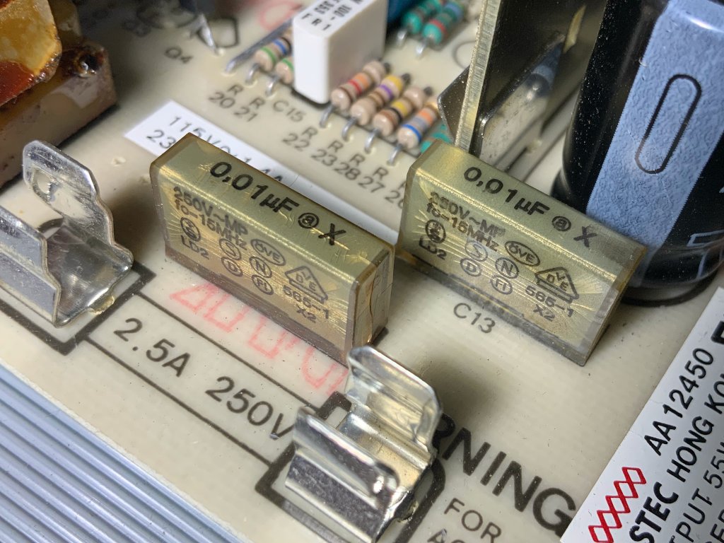
Power Supply
Yes, indeed, the power supply is an Astec and contains Rifa capacitors, which, at their advanced age are liable to smoke and stink at some point.
TODO: Have I replaced the Rifa capacitors?
Floppy Drives
Half-height, with push-button (head load mechanism?). From section 9 of the technical manual, these drives appear to be Epson.
Maintenance Log
The system will boot just fine from a Gotek floppy emulator running FlashFloppy. TODO: Document any interesting configuration or jumper settings.