Dynalogic Hyperion
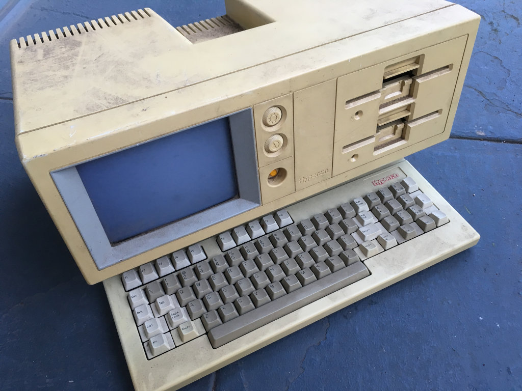
TODO: Clean image of computer.
Computers in Collection
General Info
Display and I/O Board
Board “REV09 0364”.
| Part | Description | Markings | Function | Dimensions | Color | Test Result | Replacement |
|---|---|---|---|---|---|---|---|
| C1 | 22uF 10%, 35V, tantalum | 226 +35K | +5V supply | 3mm lead spacing, 6.35mm hole pitch, ~7mm diameter | Orange | 1kHz c=22.5uF d_apo=0.042 | |
| C9 | 33uF 10%, 6.3V, tantalum | +5V supply | 3mm lead spacing, 5mm hole pitch, ~5mm diameter | Orange | 1kHz c=33.1uF d_apo=0.381 | ||
| C11 | 33uF 10%, 16V, tantalum | 336 +15K | -12V supply | 3.5mm lead spacing, 5mm hole pitch, ~6.5mm diameter | Orange | 1kHz c=30.6uF d_apo=1.072 | AVX TAP336K016CCS |
| C27, C30 | 22uF 20%, 10V, tantalum | ||||||
| …others… | “336” (33uF?), tantalum | 336 +??K | 5mm hole pitch |
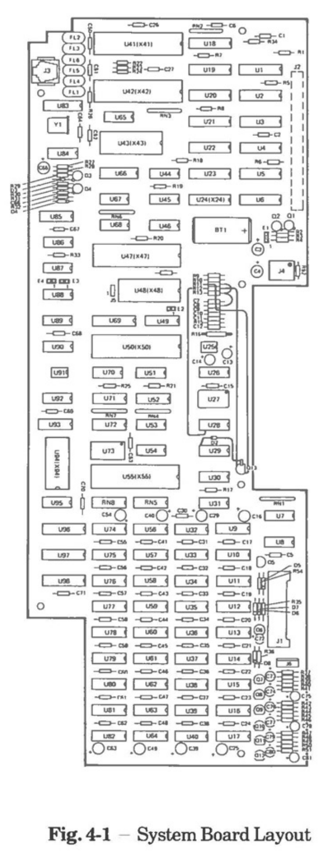
System Board
Board “REV. 12.2”.
| Part | Description | Markings | Function | Dimensions | Color | Test Result | Replacement |
|---|---|---|---|---|---|---|---|
| C3 | 33uF 10%, 6.3V, tantalum | 33 6 | on +5V supply | 3mm lead spacing, 5mm hole pitch, ~4mm diameter | Blue | 1kHz c=31.5uF d_apo=0.208 | |
| C4 | 33uF 10%, 16V, tantalum | 336 +16K | on +12V supply | 4mm lead spacing, 5mm hole pitch, ~6.5mm diameter | Orange | 1kHz c=32.2uF d_apo=0.155 | |
| C13 | 22uF 10%, 35V, tantalum | 22 +35 | LM386 bypass pin | 5mm lead spacing, 5mm hole pitch, ~7mm diameter | Blue | 1kHz c=21.4uF d_apo=0.082 | |
| C14 | 47uF 20%, 16V, tantalum | 47 +16 | LM386 audio out DC block | 5mm lead spacing, 5mm hole pitch, ~7mm diameter | Blue | 1kHz c=44.5uF d_apo=0.089 | |
| C72 | 47uF 20%, 16V, tantalum | 47 +16 | across +12V in fan circuit | 5mm lead spacing, 5mm hole pitch, ~7mm diameter | Blue | 1kHz c=46.4uF d_apo=0.139 | |
| C16, C25, C29, C39, C40, C49, C54, C63 | 4.7uF 10%, 6.3V, tantalum | 4.7 6 | 5mm lead spacing | ||||
| C73, C76, C79 | 220nF 20%, 35V, tantalum | ||||||
| C74, C77, C80 | 2.2uF 20%, 16V, tantalum | ||||||
| C75, C78, C81 | 10uF 20%, 16V, tantalum | ||||||
| C65 | 10uF 10%, 6.3V, tantalum |
Modem Board
TODO: Catalog components, note board revision/date.
Power Supply
Astec model number AA12310. Possible replacement with Mean Well RT-85B? It depends on if having two separate +12V supplies (one for the logic and one for the CRT) is important. I’m thinking it’s not…?
Output voltages:
| Supply | Voltage / Current | Function |
|---|---|---|
| V1 | +5V, 7.3A | |
| V2 | +12V, 1.25A | |
| V3 | +12V, 1.25A | |
| V4 | -12V, 0.1A |
Connector TB2
Replacement part? Molex 0026604130
Pinout:
| Signal | Voltage | Function |
|---|---|---|
| COM | ||
| COM | ||
| COM | ||
| V1 | +5V | |
| V1 | +5V | |
| V1 | +5V | |
| V3 | +12V (main) | |
| V3 | +12V (main) | |
| V3 | +12V (main) | |
| V4 | -12V | |
| Key | ||
| V2 | +12V (aux) | |
| COM |
Replacement parts:
| Part | Description | Lead Spacing | Diameter | Height | Original Markings | Substitution |
|---|---|---|---|---|---|---|
| C5, C6, C7, C8 | 100uF, 250V, +105C | 8mm, radial | 18mm | 41mm | Marcom, “CE-US 8334 3VB” or “CE-US 8329 3UB” | Nichicon UCA2E101MHD |
| C9 | 220uF (M), 10V, 105C | 5mm, radial | 10mm | 16.5mm | Nippon Chemicon?, “SXA CE04C”, “37 E (2)” | Nichicon UPW1V221MPD |
| C17, C18 | 1000uF (M), 16V, +105C | 7.5mm, radial | 16mm | 26mm | Nippon Chemicon?, “SXA CE04C”, “33 P (2)” | Nichicon UPJ1C102MHD6 |
| C19, C20 | 2200uF (M), 10V, +105C | 7.5mm, radial | 16mm | 31mm | Nippon Chemicon?, “SXA CE04C”, “38 S (2)” | Nichicon UPJ1C222MHD6 |
| C21, C25 | 100uF (M), 25V, +105C | 5mm, radial | 10mm | 16.5mm | Nippon Chemicon?, “SXA CE04C”, “38 W (2)” | Nichicon UPW1J101MPD |
| C22, C23, C24 | 2200uF, 16V, 85C | 7.5mm, radial | 16mm | 25mm | Rubycon, “CE W M 172” or “CE W M 199” | Nichicon UPJ1C222MHD6 |
| L1, L2 | RF choke, toroidal | 7.5mm, radial | 15mm | 7.5mm | 0.6mm lead diameter, measured 88uH and 0.05 Ohms DC resistance | Wurth 7447021 or 7447033? |
Hyperion, unknown serial
I acquired this machine from a basement trove of mid-80s stuff – IBM ATs, Apple IIgses, Commodore Plus/4s, and lots of PC clones.
- Display and I/O board: “DYNALOGIC INFO-TECH CORPORATION PWA-100005”, “REV09 0364”.
- System board: “DYNALOGIC INFO-TECH CORPORATION” “PWA-100004-?” “REV. 12.2” with an unintelligable serial number.
- Modem board: “PWA 100012-000-__”, “PWB 200014-000–01” (I think), “SER NO.”, “REV08 0924”.
- Power supply: Astec model number AA12310, serial number 172025926, date T8340.
Repair Log
Case Cleaning
Removed front face, rear casing, and keyboard skids. Scrubbed with Windex in a hot shower.
Bring-Up
Removed main PCBs. Disconnected power from floppy drives. Disconnected video/power cable from CRT assembly.
Powered on with front button. Switching regulator made rapid snapping sound. Viewed voltage rails with oscilloscope, where regulated voltages would start rising, then drop to zero, several times a second. Apparently these supplies don’t like running without load?
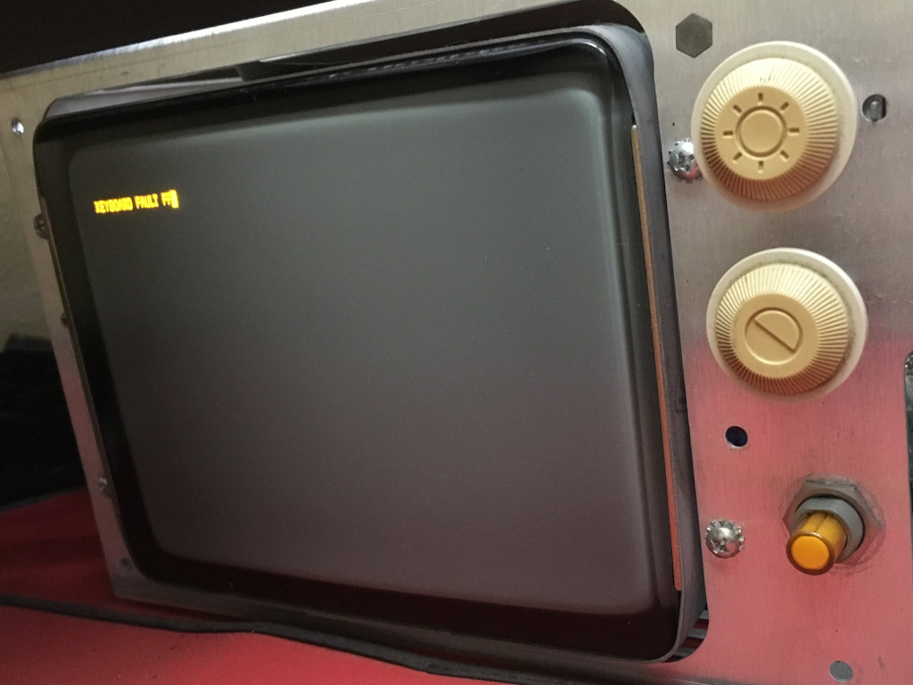
Retried with floppy drives connected. (YOLO!) No power supply snapping! Checked the voltage rails and they look sane. Re-attached CRT and main PCBs. CRT takes a long time to warm up, and I hear a somewhat disconcerting but quiet hiss/buzz from the CRT circuitry. But the CRT works! The system came up with a beautiful amber “KEYBOARD FAULT FF” message. Which is fine because I didn’t plug in the keyboard…
After powering down, the computer still made a light hiss. Maybe fifteen seconds later, it died out. I suspect a capacitor somewhere is not healthy, though I see no physical evidence of it.
I did clean the CRT anode and replace the dielectric gel at some point.
Powered on again with the keyboard plugged in, and all I get on the screen is a blinking cursor. However, the drive LEDs ping pong back and forth (silently?!), so it’s definitely trying to load something! Do I have any old MS-DOS floppies laying about? I kinda think not… (Apparently I didn’t wait long enough to get the “DISK FAULT” message?)
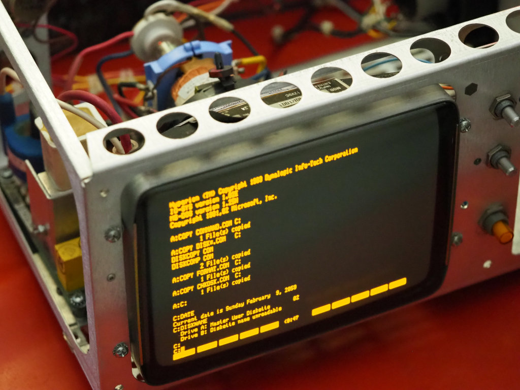
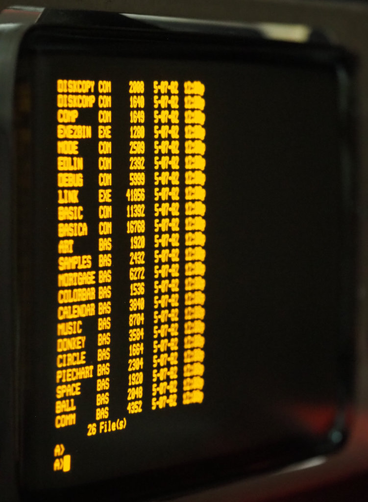
Found an MS-DOS 3.1 boot disk, tried it, and it works! Kinda… DOS freezes after a time, however. Power issues? Bad RAM?
Amber CRTs are sooooo nice.
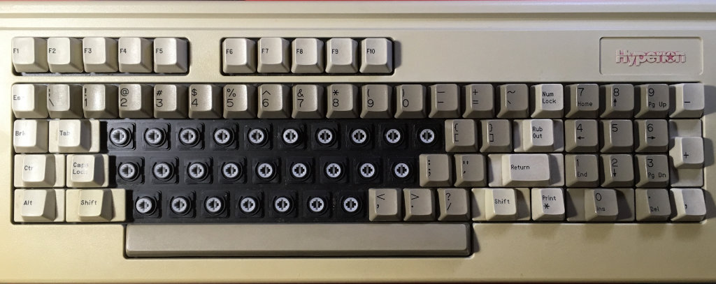
Keyboard
Disassembled keyboard. I wasn’t sure how to remove the six retaining clips, and succeeded in breaking one of the plastic posts and cracking a couple of the others. It turns out there’s guidance about how to remove those clips in the Hyperion manuals…
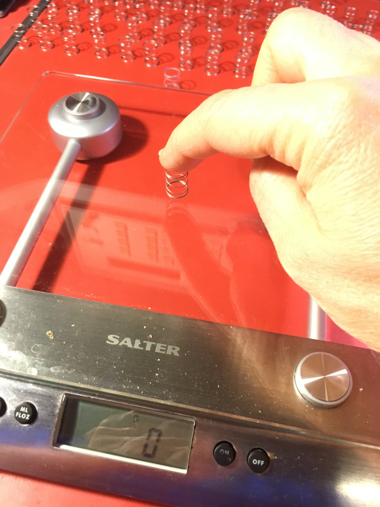
Measured keyboard springs as I was removing them, in case any were stronger or weaker (sometimes done for special keys like the space bar or function keys)
Scrubbed keyboard plastic housing with Windex and a brush.
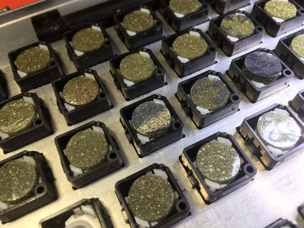
Opened Keytronic assembly, foam was deteriorated and crumbly, most of the metalized pads were no longer metalized. Fortunately, newly-manufactured foam/mylar capacitive pads are available from TexElec, so I ordered some to try out.
Pulled the rigid plastic retainer circles from each key plunger, and saved them for later reassembly.
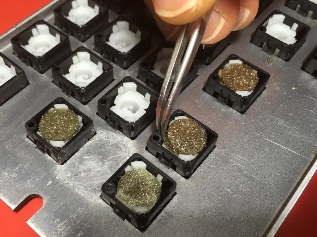
Removed key caps and soaked in three squirts of OxyClean and some borax and some water heated to 160F for a few hours. After drying, reassembled with lithium grease lubrication on each plunger stem.
After putting everything back together, the keyboard works! However, I do get a “KEYBOARD FAULT AB0E” periodically, which seems to mean the RUB OUT key is stuck? OK, wait… A lot of keys don’t work. I’ve popped out the non-working ones and replaced them with other pads from the pack I ordered, and somehow that’s fixed almost all of them. I also gave the circuit board a quick rub-down with a red ScotchBrite pad followed by an isopropyl cleaning pass, though that didn’t address any of the inoperative keys. At the end, almost all the keys work, though a few work too well, and register keypresses if they’re even jiggled laterally (not pressed), which means they also sometimes register if typing firmly on other keys.
Floppy Emulation
I’m using a GoTek with the FlashFloppy firmware. I’ve removed the “JC” jumper (selecting Shugart interface) and installed the “S0” jumper to have the emulator act as drive A. Move the “S0” jumper to “S1” to emulate the B drive instead.
Power Supply
Output is 68W max. It doesn’t like running with no load, and will make a snapping sound repeatedly as the switching regulator goes overvoltage and restarts.
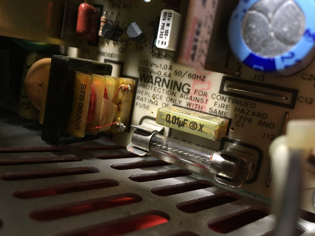
During re-assembly, I noticed that one of the toroid, wire-wound inductors (L2) looked very toasty. The heat shrink was a bit melted and burnt. On the solder side of the PCB, under this inductor, the PCB looked a bit charred. I probably shouldn’t trust this power supply, and should start shopping for a replacement.
Pulled all electrolytic capacitors. C5 measured 30uF (not 100uF). C8 measured 8nF (not 100uF).
2018/Sep/11: All power supply X (Rifa) and electrolytic capacitors and two line filter inductors replaced.
Maintenance Log
2018/Sep/11
Floppy drives greased (but not oiled – oil is at the office) and slightly cleaned.
2019/Mar/18
Cleaned off CRT anode area. Replaced dielectric grease with Permatex #22058. TODO: I may have made a mistake and cleaned off the Aquadag! Or am I remembering a Kaypro I did this to? The aquadag looks fine.
2019/Apr/05
Got the Gotek with FlashFloppy firmware to boot a IBM PC-DOS 2.1 floppy image. CRT started to get quite flaky and produce no output. Sketchy composite output still available via the RCA, but it’s a bit strange it’s so sketchy…
2019/Apr/06
Tantalum capacitor C11 on the display board smoked and spit tantalum on my hand. Ouch! Looking for a 33uF 16V replacement…
2021/Nov/7-10
Battling with “PARITY FAULT” messages and a frozen computer when trying to boot the diagnostics disk. I put together a DRAM checker Saleae analyzer, which checks that every read value matches the value last written. Doing this, I proceeded to identify a defect in each and every one of the bank 0 (U9-17) DRAMs. The old TMS4164-15NLs were removed and replaced with M5K4164NS-20 in machined sockets. Doing this got me to the point of being able to boot the diagnostics and choose the RAM test, which now fails with a “PARITY FAULT” at a consistent address in bank 1 (U32-40).
2021/Nov/10
Unsocketed all socketed ICs on the system board – U41 (D8088), U43 (D8259AC), U47 (P8237A-5), U48 (AM2764-3), U50 (D765AC), U55 (AM2964BPC), U94 (D8253C-5), U100 (SN74LS393N). All sockets had some amount of green residue, as did the ICs from those sockets. I’m not sure if it’s corrosion, as it doesn’t seem particularly crusty, but almost like a green ink. But I dumped a bunch of DeoxIT D100L into the socket pin cavities. No notable changes in behavior were observed. :-(
2021/Nov/10
Removed the E1 jumper, which connects the battery to the XRTC VDD net. Since the battery is most certainly dead and should be removed, I figured it’d do no harm.
| Jumper | State (as found) | Function |
|---|---|---|
| E1 (2 pins) | Installed 1-2 | 1-2: XRTC VCC net |
| E2 (3 pins) | Open | U48 EPROM size/pinout |
| E3 (2 pins) | Open | Jumper readable by STATUS# |
| E5 (3 pins) | Rework wire between 1 and 3, 2 wired to U65 pin 7 (ground?). | CRT/PARITY ERROR interrupt routing |
| E6 (2 pins) | Open | |
| E7 (2 pins) | Installed 1-2 | |
| E8 (2 pins) | Installed 1-2 |
2021/Nov/10
Took a look at the DACK0#/RFSH# signal, which is supposed to cause the Am2964B to perform a RAS#-only refresh of the DRAM. Guess what? It doesn’t budge! It never changes from high. So my RAM isn’t getting refreshed at all. It’s a bit surprising the system is working at all! DACK0# isn’t coming out of the DMAC chip. And DREQ0 on the DMAC chip isn’t doing anything either. DREQ0 comes from U31.6 – no life, always low. The input on the U31 flip-flop is on pin 3, and it’s also inactive, always low. That signal comes from U100.11, which is one of the chips with the corroded socket. There’s nothing happening on U100.11. It looks like U100 (74LS393) is configured as a counter-divider, incremented by pin 1, with a carry between 4-bit counters on pin 13. Hey, U100.1 has a signal, about 2.4MHz! Is the carry from U100.6 to U100.13 happening? Nope! How about the other counter outputs clocked by U100.1 (pins 3, 5, 6, 7)? There’s NOTHING coming out of U100. OK, so I’ll replace U100 and its socket, since it’s so gnarly and green. I found a 74HC393, which is technically not quite the right replacement for U100’s original “LS” logic. But it works fine in practice. And I’ve since found a 74LS393 among my accumulation of logic ICs that I’ll use as a final replacement, once I change the socket for a better, machined socket (not the corroded cheap socket I found in the system). I need to order some good 14-pin DIP sockets. All I have right now are 16-, 18-, and higher pin-count sockets.
2023/Nov/30
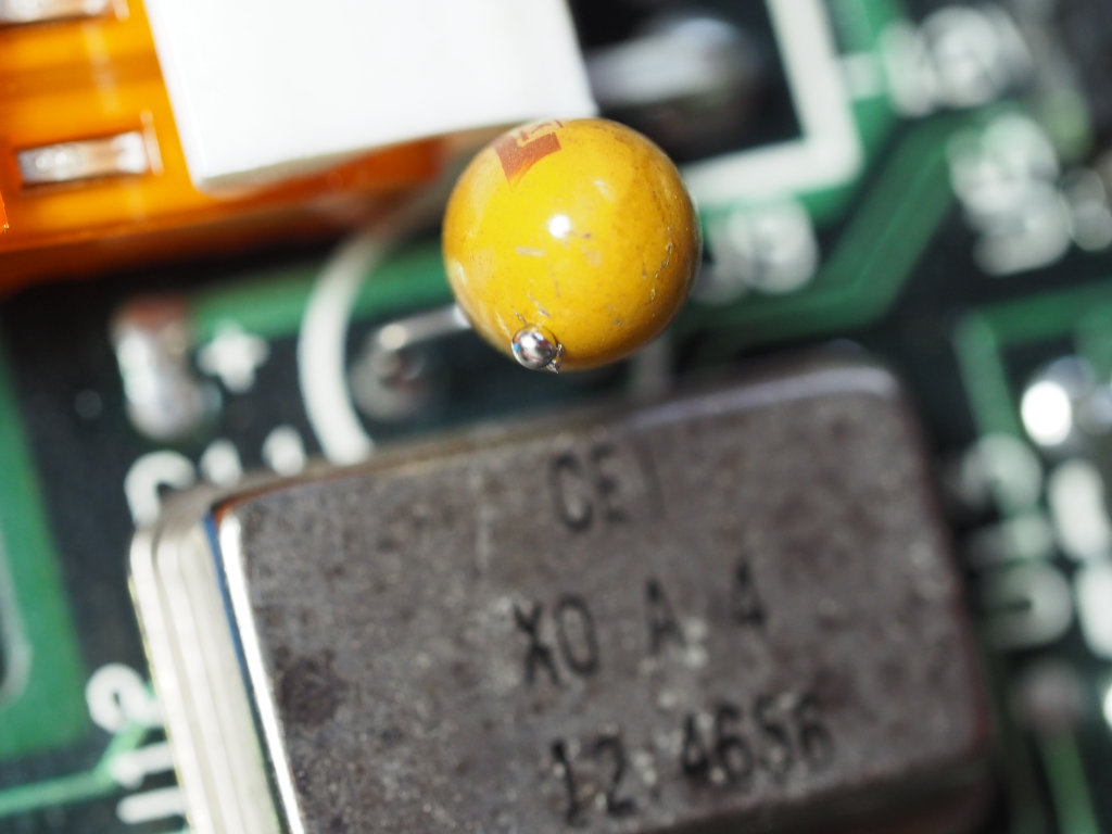
Attempted power-on and there was only a few moments of rapid ticking followed by a small “snap”. I immediately powered it back off. Upon investigation, it seems tantalum capacitor C4 was unhappy, shorted the (+12V?) supply, then blew out. To wit:

Hopefully there was no related damage. I really need to swap out all the tantalums, or this is going to keep happening. I also need to remember to inspect the system board to make sure there’s no loose bits of tantalum hanging around. Given my previous experience with this system and its tantalums, it’s definitely a possibility.
I tested the +5V and +12V rails on the system board and discovered that there was a short on the +12V rail. That’d be the rail that capacitor C4 is on. I extracted C4 and tested its resistance, and it was a disgraceful 0.14 Ohms! Testing the +12V rail again showed more reasonable results in the 10s of k-Ohms or higher. I replaced C4 with a new 33uF, 16V tantalum I had on-hand, likely the AVX TAP336K016CCS I mentioned as my replacement for the display board’s C11. The system now boots as well as it usually does, which is to say it was throwing “KEYBOARD FAULT AB2B” or something like that, because the keyboard is a mess.
There’s probably a keyboard matrix diagram in the maintenance or reference manuals. Sure enough, in volume 1 of the maintenance manual, under the “Hyperion-On-Self-Test (HOST)” section, a keyboard fault code of the form “ABXX” is reported where “XX” is the key number of the stuck key. I think by “key number”, they mean “scan code”. In the technical reference guide, pages III-25 through 27, there’s table III-I, which shows “0E” == “Rub Out”, and “2B” == “". Very helpful. I should try repairing those keys and see if I can get past this.
| Scan Code | Lower Case | Upper Case | Ctrl + | Alt + |
|---|---|---|---|---|
| 01 | Esc | Esc | Esc | N.A. |
| 02 | 1 | ! | N.A. | (Note) |
| 03 | 2 | @ | NUL (Note) | (Note) |
| 04 | 3 | # | N.A. | (Note) |
| 05 | 4 | $ | N.A. | (Note) |
| 06 | 5 | % | N.A. | (Note) |
| 07 | 6 | ^ | RS | (Note) |
| 08 | 7 | & | N.A. | (Note) |
| 09 | 8 | * | N.A. | (Note) |
| 0A | 9 | ( | N.A. | (Note) |
| 0B | 0 | ) | N.A. | (Note) |
| 0C | ↑ | _ | US | (Note) |
| 0D | = | + | N.A. | (Note) |
| 0E | Rub Out | Rub Out | DEL | (Note) |
| 0F | Tab | Backtab | N.A. | (Note) |
| 10 | q | Q | DC1 | (Note) |
| 11 | w | W | ETB | (Note) |
| 12 | e | E | ENQ | (Note) |
| 13 | r | R | DC2 | (Note) |
| 14 | t | T | DC4 | (Note) |
| 15 | y | Y | EM | (Note) |
| 16 | u | U | NAK | (Note) |
| 17 | i | I | HT | (Note) |
| 18 | o | O | SI | (Note) |
| 19 | p | P | DLE | (Note) |
| 1A | [ | { | Esc | (Note) |
| 1B | ] | } | GS | (Note) |
| 1C | Rtn | Rtn | LF | (Note) |
| 1D | N.A. | N.A. | N.A. | (Note) |
| 1E | a | A | SOH | N.A. |
| 1F | s | S | DC3 | N.A. |
| 20 | d | D | EOT | (Note) |
| 21 | f | F | ACK | (Note) |
| 22 | g | G | BEL | (Note) |
| 23 | h | H | BS | (Note) |
| 24 | j | J | LF | (Note) |
| 25 | k | K | VT | (Note) |
| 26 | l | L | FF | (Note) |
| 27 | ; | : | N.A. | N.A. |
| 28 | ’ | ” | N.A. | N.A. |
| 29 | ` | - | N.A. | N.A. |
| 2A | Shift | Shift | Shift | (Note) |
| 28 | \ | | | FS | (Note) |
| 2C | z | Z | SUB | (Note) |
| 20 | x | X | CAN | (Note) |
| 2E | c | C | EXT | (Note) |
| 2F | v | V | SYN | (Note) |
| 30 | b | B | STX | (Note) |
| 31 | n | N | SO | (Note) |
| 32 | m | M | Rtn | (Note) |
| 33 | , | < | N.A. | N.A. |
| 34 | . | > | N.A. | N.A. |
| 35 | / | ? | N.A. | N.A. |
| 36 | Shift | Shift | Shift | Shift |
| 37 | * | (Note) | N.A. | |
| 38 | Alt | Alt | Alt | Alt |
| 39 | spacebar | spacebar | spacebar | spacebar |
| 3A | Caps Lock | Caps Lock | Caps Lock | Caps Lock |
| 38 | F1 (Note) | N.A. | N.A. | (Note) |
| 3C | F2 (Note) | N.A. | N.A. | (Note) |
| 30 | F3 (Note) | N.A. | N.A. | (Note) |
| 3E | F4 (Note) | N.A. | N.A. | (Note) |
| 3F | F5 (Note) | N.A. | N.A. | (Note) |
| 40 | F6 (Note) | N.A. | N.A. | N.A. |
| 41 | F7 (Note) | N.A. | N.A. | N.A. |
| 42 | F8 (Note) | N.A. | N.A. | N.A. |
| 43 | F9 (Note) | N.A. | N.A. | N.A. |
| 44 | F10 (Note) | N.A. | N.A. | N.A. |
| 45 | Num Lock | N.A. | Pause | N.A. |
| 46 | N.A. | N.A. | Break | N.A. |
| Scan Code | Num Lock ON | Num Lock OFF | Ctrl + | Alt + |
|---|---|---|---|---|
| 47 | 7 | Home (Note) | (Note) | N.A. |
| 48 | 8 | ↑ (Note) | (Note) | N.A. |
| 49 | 9 | PgUp (Note) | (Note) | N.A. |
| 4A | - | - | N.A. | N.A. |
| 4B | 4 | ← (Note) | (Note) | N.A. |
| 4C | 5 | N.A. | (Note) | N.A. |
| 4D | 6 | → (Note) | (Note) | N.A. |
| 4E | + | + | (Note) | N.A. |
| 4F | 1 | End (Note) | (Note) | N.A. |
| 50 | 2 | ↓ (Note) | (Note) | N.A. |
| 51 | 3 | PgDn (Note) | (Note) | N.A. |
| 52 | 0 | Ins | (Note) | N.A. |
| 53 | Del | (Note) | N.A. |
N.A = Not Applicable Note: Refer to Table III-J for non-ASCII characters.
I’m still dreading the next step, as I think I did get the system to boot past the keyboard fault once. There was a fault, but I couldn’t read the whole message due to the text being partially off-screen. I could only make out “Y FAULT”, which worries me because the full message is probably “PARITY FAULT”. Or “MEMORY FAULT”. Both have the same last seven characters. Though I would’ve thought it’d report an address or something, too.