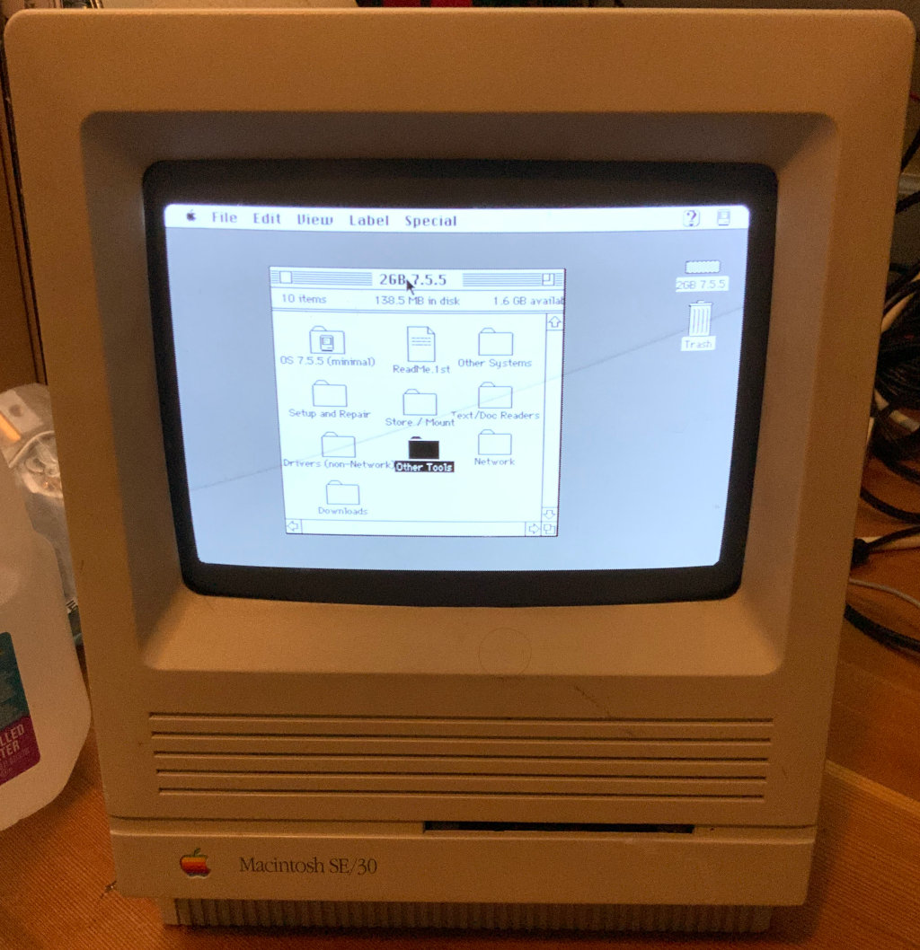
Apple Macintosh SE/30
Computers in Collection
- Apple Macintosh SE/30, model M5119, serial F102878EB03
- Apple Macintosh SE/30, model M5119, serial F9102RUK03
General Info
Replacement Components
Capacitors
The surface-mount capacitor replacements are solid-electrolyte capacitors, which should not leak and should last much longer than the originals.
| Ref | Value | Package | Function | Equivalent |
|---|---|---|---|---|
| C1 | 47uF, 16V, 85C | SMT 6.5mm x 6.5mm, 6.1mm height, 6.3mm radius | +5V bypass | Kemet A765EB476M1ELAE040 |
| C2 | 470uF, 16V, 85C | TH axial 21.6mm length, 10mm radius | +12V audio supply filter | TODO: |
| C3 | 47uF, 16V, 85C | SMT 6.5mm x 6.5mm, 6.1mm height, 6.3mm radius | Sound out DC block, left | Kemet A765EB476M1ELAE040 |
| C4 | 47uF, 16V, 85C | SMT 6.5mm x 6.5mm, 6.1mm height, 6.3mm radius | Sound out DC block, right | Kemet A765EB476M1ELAE040 |
| C5 | 47uF, 16V, 85C | SMT 6.5mm x 6.5mm, 6.1mm height, 6.3mm radius | Sound Vref bypass | Kemet A765EB476M1ELAE040 |
| C6 | 1uF , 50V, 85C | SMT 4.3mm x 4.3mm, 5.9mm height, 4.1mm radius | Sound internal bypass? | Nichicon UUD1H010MCL1GS |
| C7 | 47uF, 16V, 85C | SMT 6.5mm x 6.5mm, 6.1mm height, 6.3mm radius | +5V bypass | Kemet A765EB476M1ELAE040 |
| C8 | 47uF, 16V, 85C | SMT 6.5mm x 6.5mm, 6.1mm height, 6.3mm radius | Power connector -5V | Kemet A765EB476M1ELAE040 |
| C9 | 47uF, 16V, 85C | SMT 6.5mm x 6.5mm, 6.1mm height, 6.3mm radius | Power connector -12V | Kemet A765EB476M1ELAE040 |
| C10 | 47uF, 16V, 85C | SMT 6.5mm x 6.5mm, 6.1mm height, 6.3mm radius | Power connector +12V | Kemet A765EB476M1ELAE040 |
| C11 | 220uF, 16V, 85C | TH axial 16.1mm length, 8.3mm radius | Power connector +5V | TODO: |
| C12 | 47uF, 16V, 85C | SMT 6.5mm x 6.5mm, 6.1mm height, 6.3mm radius | +5V bypass | Kemet A765EB476M1ELAE040 |
| C13 | 47uF, 16V, 85C | SMT 6.5mm x 6.5mm, 6.1mm height, 6.3mm radius | +5V bypass | Kemet A765EB476M1ELAE040 |
Transistors
| Ref | Value | Package | Function | Equivalent |
|---|---|---|---|---|
| Q3 | 2N3904 | Identified from schematic 050-0253-01 (rev “D”?), page 4 of 9 | ADB-related | TODO: |
Fan
Existing fan is 12V DC and 55 to 70 mA – Sanyo 109P0612M414 “DC Pico Ace 25” or Elina HDF6025L-12MB-1. The fan blows outward – drawing air from inside the case. Mounting holes are spaced 50 mm apart and are approximately 4 mm in diameter. Case dimensions are 60 mm x 60 mm x 25 mm. Cable is two-conductor (power and ground) and I eyeball it as less than a foot long. Relatives of this fan are still being sold at Digi-Key! I’m guessing, based on similar part numbers that the old part is approximately 13 CFM and 2600 RPM. Assuming the new models are as quiet as the old one, the noise is 20.0dB(A).
Several fans look to be good replacements and might be quieter than the original. Particularly the Sunon HA60251V4-1000U-A99 and CUI CFM-6025V-125-107-20.
It’s quite annoying that they glued (with hot glue?) the fan wires at several points along the analog board!
Apple Macintosh SE/30, serial F102878EB03
Inventory
Received from Glenn via Sean@CCC on 2020/Dec/06.
Case
| Attribute | Value |
|---|---|
| Manufacturer | Apple |
| Model | M5119 |
| Serial | F102878EB03 |
| Exterior Markings | Sticker: “KVO Advertising & Public Relations Asset No. 0143” |
| Internal Markings | “21 MAY 1992” “815-1145” |
| Source | 2020/Dec/06, Glenn via Sean@CCC |
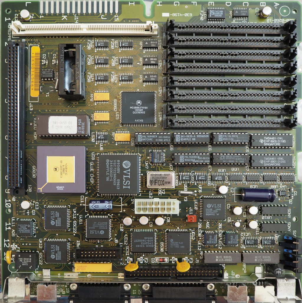
Logic Board
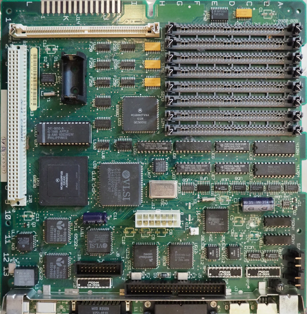
NOTE: Battery, electrolytic capacitors, ROM SIMM, and RAM SIMMs removed in the above photo.
| Attribute | Value |
|---|---|
| Manufacturer | Apple |
| Part | 820-0260-A |
| Serial | CK2200P600YC |
| Markings | “Apple Computer Inc. (C) 1989”, handwritten sticker “92/22/DR/U” |
| Solder Mask | standard green |
| SIMM Clips | metal |
| CPU | Motorola MC68030RP16B (black package), no socket |
| PALs | soldered |
| Video ROM | 341-0650-A “(C) 1988 Apple” “AMI 9203MEW Philippines” |
| Source | 2020/Dec/06, Glenn via Sean@CCC |
C12 capacitor is closer to battery on this board vs. the BK9014566 board.
RAM
| Qty | Module Markings | IC Markings |
|---|---|---|
| 1 | “MH1M08B0J-8 USA 1153GB7” | 8 x Mitsubishi M5M4100BJ-8 “112NEMH” |
| 1 | “MH1M08B0J-8 USA 1153GB7” | 8 x Mitsubishi M5M4100BJ-8 “114NEBT” |
| 1 | “M9201-001” | 8 x Motorola MCM511000AJ80 “UQQAP8951” “UQQAG8950” “UQQAN8951” “UQQAH8950” “UIQAA8943” “UQQAH8951” “UQQAH8951” |
| 1 | “M9201-001” | 8 x Motorola MCM511000AJ80 “UQQBA8948” “UQQAD8947” “UQQAY8949” “UQQBE8948” “UQQAB8949” “UQQBG8948” |
| 1 | “MB85230-10 Japan 8946 T43” | 8 x Fujitsu 81C1000-10 “8930 T08 PJ” |
| 1 | “MB85230-10 Japan 8946 T43” | 8 x Fujitsu 81C1000-10 “8930 T09 PJ” |
| 1 | “OPC 09-91 120009-A1” | 8 x NMBS AAA1M300J-08 “9125” |
| 1 | Toshiba THM81000AS-10 “8910AAA Japan” | 8 x Toshiba TC511000AJ-10 “Japan 8910HCK” |
ROM
| Attribute | Value |
|---|---|
| Style | SIMM |
| Design | two ICs |
| Markings | “7788A1 Toshiba” “341-0655-A (C) 88 Apple T9A70-F750-1” “9207AAA Japan” |
| Source | 2020/Dec/06, Glenn via Sean@CCC |
High Voltage Board
TODO:
Internal Power Supply
| Attribute | Value |
|---|---|
| Manufacturer | Sony |
| Model | CR-44 |
| Part | 68-1074-01 |
| Serial | 231692 |
| Other Manufacturer | Taiwan Toyo Radio Co. Ltd. |
| Other Part No. | 699-5047 |
| Markings | “8802” |
| Source | 2020/Dec/06, Glenn via Sean@CCC |
Internal Cathode Ray Tube
TODO:
Internal Floppy Drive
TODO:
Internal Hard Drive
| Attribute | Value |
|---|---|
| Manufacturer | Maxtor |
| Model | 7120SR |
| Assembled In | “MHK” |
| HDA | 22A |
| PCBA | S55A |
| Unique | 37A |
| DM | 2332E |
| Uplevel | “K004970751” “Z,Z,B” “A2170LLS” “3235 35” “2992” |
| Markings | “Inspected by: 02 Sep 1992 Maxtor Quality” “19610” |
| Notes | Backed up via SCSI2SD |
| Source | 2020/Dec/06, Glenn via Sean@CCC |
Maintenance Log
2020/Dec/06
Booted up to flashing floppy with “?”. A good sign!
Opened up case, examined logic board. Missing one case screw, right side of handle. Removed battery. No obvious battery leakage.
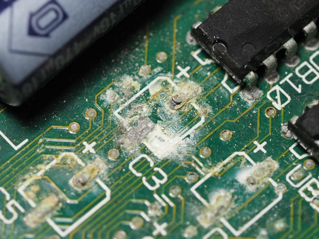
Lots of leaked capacitor electrolyte on PCB. Surface-mount electrolytic capacitors need replacement.
Several ICs near SMT capacitors have corroded pins:
- UD8 F253
- UE8 LS166
- UF8 F393
- UE10 ASC
- UB10, UB11 SONY
- UI12 SCSI
- UJ11
- UL11 ADB
- Q3
- D2
- RP1
Flyback transformer looks kinda crisp, but the lighting was bad, so I need to revisit.
2020/Dec/13
All the SMT electrolytic capacitors were removed with gentle mechanical shear stress – rocking side to side perpendicular to the axis formed by the two solder pads. Most leads remained attached to the solder on the pads. Perhaps this was because I haven’t cleaned this board at all, and if I had, the corrosion removal treatment would’ve weakened the joints significantly? Or it’s possible this board is simply less corroded, or the solder joints are better to begin with? As a result of losing legs on most of the capacitors, I don’t have a sense for how dramatically these capacitors failed.
With the exception of the 1uF capacitor, the capacitor replacements listed above are aluminum polymer electrolyte. Polymer electrolytes have many advantages, among which are that they should last much longer when operated at moderate temperatures and not leak. They are approximately double the price of equivalent-rating standard aluminum electrolytic capacitors, but for less than $2.00 per recapped machine, it’s a price I’d gladly pay to never have to clean up and replace these capacitors again.
Apple Macintosh SE/30, serial F9102RUK03
Inventory
Received from Glenn via Sean@CCC on 2020/Dec/06.
Case
| Attribute | Value |
|---|---|
| Manufacturer | Apple |
| Model | M5119 |
| Serial | F9102RUK03 |
| Markings | sticker: “Mac Shop Northwest” |
| Missing | accessory cover |
| Source | 2020/Dec/06, Glenn via Sean@CCC |
Logic Board
NOTE: Battery, ROM SIMM, and RAM SIMMs removed in the above photo.
| Attribute | Value |
|---|---|
| Manufacturer | Apple |
| Part | 820-0260-10, 630-4198-___ |
| Serial | BK9014566 |
| Markings | “Apple Computer Inc. (C) 1988” “T917424 C18” |
| Solder Mask | dark olive |
| SIMM Clips | plastic |
| CPU | Motorola XC68030RC16B (ceramic package), socketed |
| PALs | socketed |
| Video ROM | 341-0650-01 “(C) 1988 Apple” |
| Source | 2020/Dec/06, Glenn via Sean@CCC |
RAM
| Qty | Module Markings | IC Markings |
|---|---|---|
| 4 | Motorola MCM81000S “SNK NST4” | 8 x MCM511000AJ10 “UIQAD8922” |
| 4 | Upgrade Man “GT-3009” “FUYU 20V0” “9320” | 8 x AAA1M300J-08 “NPNX 9407 D1” |
ROM
| Attribute | Value |
|---|---|
| Style | SIMM |
| Design | four ICs |
| Markings | “820-0241-02 1988” “079C” “630-4339___” “Apple Computer” “1988” “MAR 02 PM” |
| Source | 2020/Dec/06, Glenn via Sean@CCC |
Internal Power Supply
TODO:
Internal Floppy Drive
TODO:
Internal Hard Drive
| Attribute | Value |
|---|---|
| Manufacturer | Quantum |
| Product | ProDrive |
| Model | 40S (?) |
| Made In | Japan |
| Case Markings | “40904170561” “40S” “0058” “940-40-9402” |
| PCB Markings | “Quantum (C) 1988” “ASSY NO 800-09-93 2.1 0” |
| EPROM Markings | “TA200 (C) 1988 QNTM CORP DisCache” |
| Notes | Spins and responds over SCSI but doesn’t become ready. Had an activity LED hooked up! |
| Source | 2020/Dec/06, Glenn via Sean@CCC |
Maintenance Log
2020/Dec/06
Booted up to flashing floppy with “?”. A good sign!
2020/Dec/10
Removed Kensington System Saver SE. No tools were required, it just popped off after applying light force in several different directions.
Opened up case. Removed battery. No obvious battery leakage.
Lots of leaked capacitor electrolyte on PCB. Surface-mount electrolytic capacitors needed replacement.
Several ICs near SMT capacitors have corroded pins:
- UB10, UB11 SONY
- UA9 TL071
- UB8 F253
- UD8 F253
- UE8 LS166
- UF8 LS393
- UE10 ASC
- UB12 75175
- UC12 75175
- UD12 26LS30
- UI12 SCSI
- UL11 ADB
- Q3
- RP1
Removed RAM and ROM SIMM. Did not remove socketed ICs. Submerged logic board, RAM, ROM in “Nice!” distilled water and a little bit of 99% IPA. Scrubbed with a medium-sized anti-static brush. Left vertical to dry. Still a small amount of electrolyte remains between power connector and adjacent capacitors. It might make sense to replace the capacitors before doing another cleaning pass. No obvious effect on the corroded IC pins, unfortunately. I’ll need to look up the chemistry involved, to try and improve things. Wound up with a white film on the bottom of the PCB – ionic residue from flux? A little IPA diluted it so it’s not particularly visible, but I think the contamination is still there.
2020/Dec/13
Used household ammonia cleanser (ammonium hydroxide with surfactant) applied to areas of the board with corrosion. It seemed to reduce the amount of corroded material, and cotton swabs turned light blue, presumably with copper salts? Then I scrubbed the areas with an ESD-safe brush. I rinsed the board with hot tap water. Then I soaked the board in maybe two liters of hot tap water and maybe 100ml of the ammonia cleaner. While submerged, I scrubbed the board, front and back, with the brush. After an hour of soaking, I drained the tub and rinsed the board in hot water and left it to dry. The aluminum tub I used had become discolored because of an ammonia/water/aluminum oxide reaction. Hopefully it didn’t impact the board… Next time, I will use a plastic tub. The board looks spotless (no visible electrolyte or other contaminants), and the corroded joints appear improved, but still aren’t shiny at all. I suppose that’s to be expected, as some corroded surface material was removed, and the resulting surface would not be as smooth as a proper solder joint. I will look more closely when I have access to my microscope. There are a few pins (on the ADB, ASC, and 26LS30 ICs) that still have blue-green spots on them, so I’m not completely done removing the corrosion, but not sure how to remove these spots after everything I’ve done so far.
All the SMT electrolytic capacitors were removed with gentle mechanical shear stress – initially gently twisting the capacitors around the vertical axis, then rocking side to side perpendicular to the axis formed by the two solder pads. All capacitor leads ultimately detached from the solder on the solder pad, though a couple of parts initially left a single leg and their plastic base behind. The capacitors that still had both legs were measured for capacitance. Most of the 47uF capacitors measured below 1nF (yes, a factor of >10,000 less than rated), with a couple showing low nF values. The 1uF capacitor measured about 300pF (about 3,000x too low). It’s amazing this machine worked at all… There must be barely enough bulk capacitance from the ceramics on the bottom of the board.
The two radial electrolytic capacitors were also tested. The 470uF capacitor tested at 417uF and 0.59 D@1kHz, and the 220uF capacitor tested at 191uF and 0.54 D@1kHz. Both are close enough to spec for me. But… maybe I should replace them anyway.
I did another cleaning pass, first using “distilled” household vinegar (acetic acid, maybe diluted to 5% in water?). I applied the vinegar directly to the areas where electrolyte leakage had occurred, and rubbed the IC pins with cotton swabs. At some point, the Q3 solder joints were so compromised, it just popped right off. The discolored pins (presumably copper salts) quickly turned back to the appropriate metallic color. After letting it sit for a while (half an hour?), I rinsed the board a couple of times with hot tap water. All the joints seem a little cleaner and shinier, though still dull relative to solder joints that hadn’t experienced corrosion. Hopefully these will reflow nicely.
2023/Nov/19
Fired up only to discover I’d left the logic board power cable disconnected. Opened up and tested 5V and 10V supplies and they seemed reasonable. Connected logic board power and system booted up to “?” floppy just fine. Measured CRT voltage with my fancy probe – about 12.63kV. Also verified that there’s a bleeder resistor that discharges the anode to <10V in maybe 30 seconds. Case and CRT and fan area still need a good clean, they’re very dusty. And the fan is loud.