Apple Macintosh Classic
Computers in Collection
- Macintosh Classic, model M0420, serial no E0500BRM0435LL/A
- Macintosh Classic, model M0420, serial no E0442TDM0435LL/A
General Info
Replacement Components
Case Fan
Existing fan is 12V DC and 60 to 65 mA – Sanyo “DC Pico Ace 25” 109R0612M405 or Elina HDF6025L-12MBB-0, which are almost the same models as my SE/30s. The fan blows upward – drawing air from under the case. Mounting holes are spaced 50 mm apart and are approximately 4 mm in diameter. Case dimensions are 60 mm x 60 mm x 25.4 mm. Cable is two-conductor (power and ground) and I eyeball it as less than 4” long, and terminates in a two-pin 0.1” female header socket. I found a datasheet with model HDF6025L-12MB listed as 10.2 to 13.8 V, 70 mA, 0.84 W, 3000 RPM, 12.7 ft^3/min (0.36 m^3/min), 26 dB(A)/1m, 85 g.
Macintosh Classic, serial E0500BRM0435LL/A
Inventory
“Acquired” from Jenny.
Case
| Attribute | Value |
|---|---|
| Name | Apple Macintosh Classic |
| Manufacturer | Apple |
| Model | M0420 |
| Serial | E0500BRM0435LL/A |
| Manufacture Date | December 1990 |
| Source | 2004, Jenny |
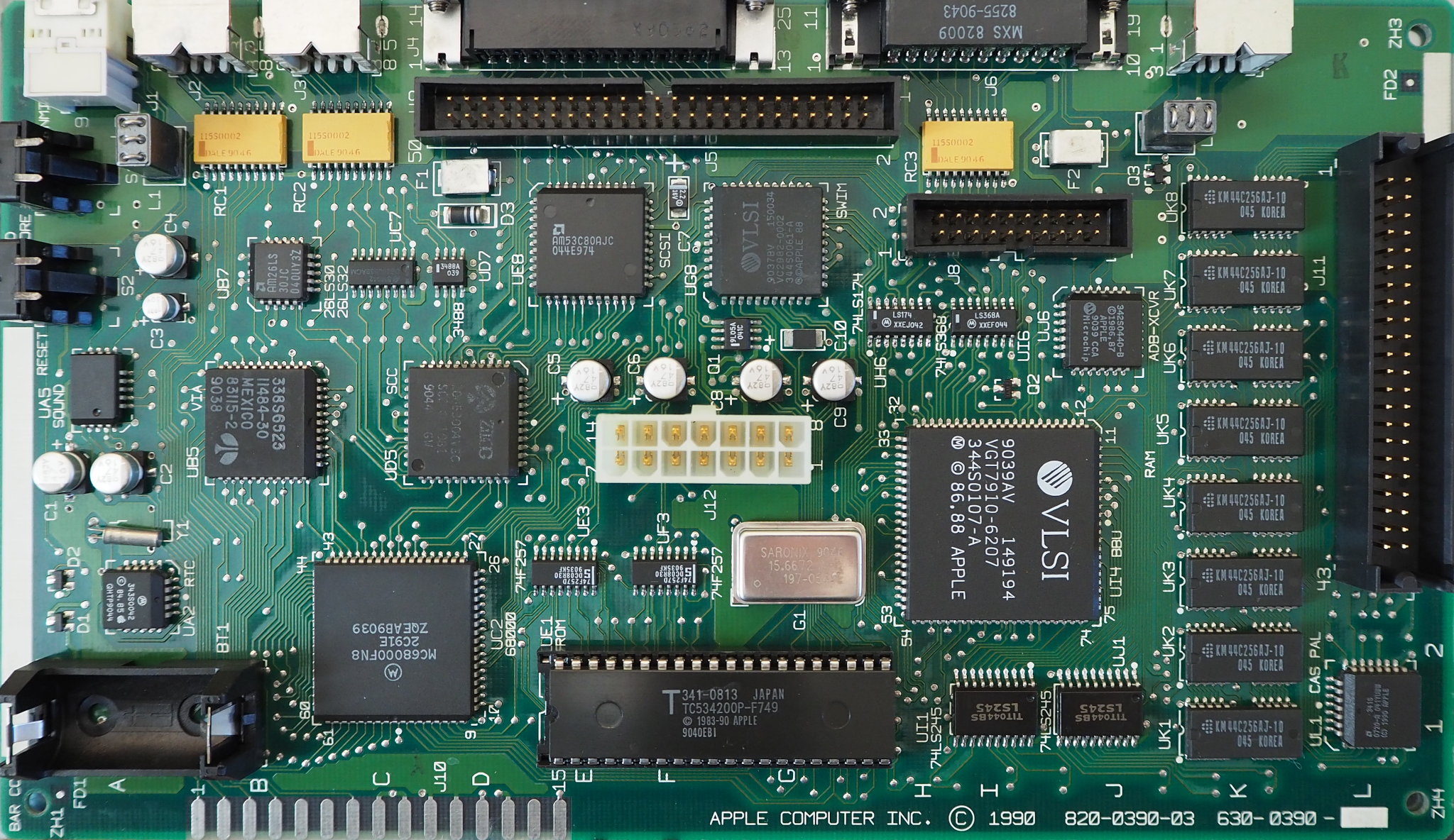
Logic Board
| Attribute | Value |
|---|---|
| Name | Apple Macintosh Classic logic board |
| Manufacturer | Apple |
| Part | TODO: |
| Bar Code | SG0508WZ03F5 |
| Solder Mask | bright green |
| Assembled In | Singapore |
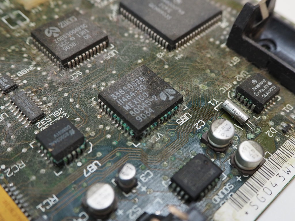
| Markings | “820-0390-03”, “630-0390-__”, serial “bar code” SG0508WZ03F5, “APPLE COMPUTER INC. (C) 1990” |
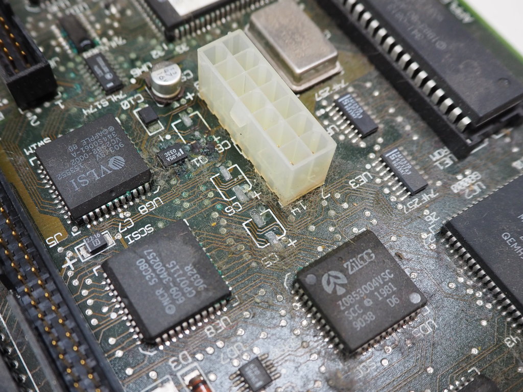
| Notes | Slight corrosion near surface-mount electrolytic capacitors. Electrolytic capacitors replaced. |
| Source | 2004, Jenny |
Memory Expansion Board
| Attribute | Value |
|---|---|
| Name | Apple Macintosh Classic memory expansion board |
| Manufacturer | Apple |
| Part | TODO: |
| Bar Code | (none) |
| Solder Mask | dark green |
| Assembled In | Singapore |
| Markings | “APPLE COMPUTER INC 820-0405-01 (C) 1990” “630-0405-S2” “470S” “G9049” “OC AHENG” |
| Source | 2004, Jenny |
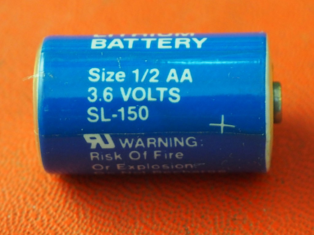
Battery
| Attribute | Value |
|---|---|
| Name | Inorganic Lithium Battery |
| Manufacturer | Sonnenschein Lithium |
| Model | SL-150 |
| Size | 1/2 AA |
| Voltage | 3.6 |
| Date Code | WX/10/90 |
| Source | 2004, Jenny |
Power Supply Board
| Attribute | Value |
|---|---|
| Name | Apple Macintosh Classic Analog Board |
| Manufacturer | Hitachi? |
| Model | |
| Serial | *SG0494KS03K4* |
| Markings | ”” |
| PCB Markings | “MAC CLASSIC ANALOG BOARD”, “(Hitachi) HCS-106C 94V-0”, “ASSEMBLED IN S’PORE”, “820-0395-C”, “630-0395-8”, “450S” |
| Date Code | L 9049 |
Internal Cathode Ray Tube
| Attribute | Value |
|---|---|
| Name | Apple Macintosh Classic internal monochrome cathode ray tube |
| Manufacturer | TODO: |
| Model | TODO |
| Serial | TODO |
| Markings | TODO: “EIA 1420” “*CL0453814801FB*” “4590” |
| Date Code | TODO: |
| Source | 2004, Jenny |
Internal Floppy Drive
| Attribute | Value |
|---|---|
| Name | Apple Macintosh Classic internal floppy disk drive |
| Manufacturer | Sony |
| Model | MP-F75W-01G |
| Serial | *SD04440600P2* |
| Made In | Malaysia |
| Source | 2004, Jenny |
Internal Hard Drive
| Attribute | Value |
|---|---|
| Name | Apple Hard Disc 40SC |
| Manufacturer | Quantum |
| Product | ProDrive LPS |
| Model | TODO: |
| Serial | TODO: |
| Made In | Japan |
| Case Markings | “440011150937” “42S 940-40-9404” “1059” |
| PCB Markings | “Quantum (C) 1989” “800-09-94 20 0” “MK 0 46 6RG 037A” |
| EPROM Markings | “J2801 (C) 1998 QNTM CORP DisCache” |
| Notes | Backed up via SCSI2SD, contents do not match source |
| Source | 2004, Jenny |
External Modem
| Attribute | Value |
|---|---|
| Name | Incomm Midget 24E Modem |
| Manufacturer | Incomm |
| Model Name | Midget 24E |
| Model Number | 0200010 |
| Serial | 0024494 |
| Source | 2004, Jenny |
Miscellaneous
| Attribute | Value |
|---|---|
| Description | DB-25 male to mini-DIN (8 pins) cable, 6 feet |
| Source | 2004, Jenny |
Maintenance Log
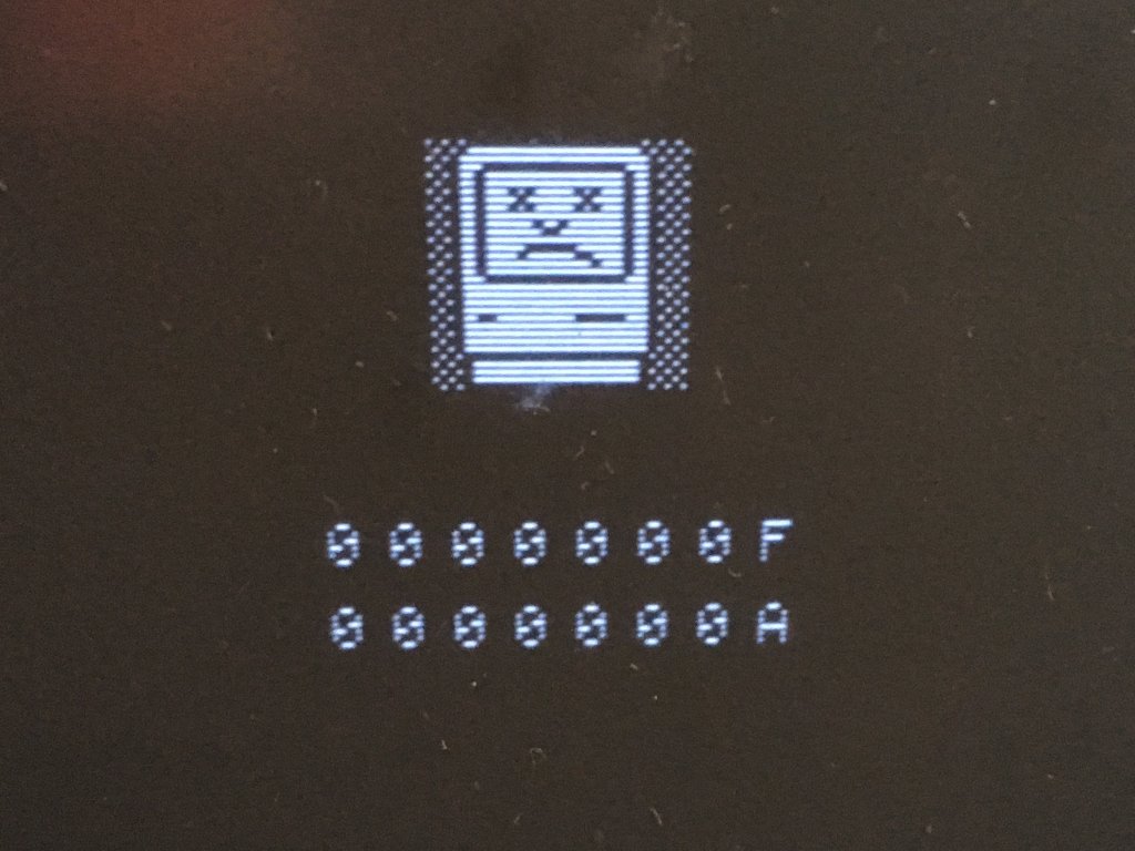
Not functional, sad Mac.
2020/Aug
Replaced SMT electrolytic capacitors (TODO: Component list. I believe this is before I got the aluminum solid polymer capacitors.). Touched up pins that appeared corroded. No improvement in “sad Mac” behavior.
2020/Mar
Tons of logic analyzer traces and ROM code reverse engineering eventually led me to suspect a VIA pin connected to the ADB chip. I compared the signals between the VIA and ADB chip at power-up, and noticed that the interrupt signal from the ADB chip was asserted earlier on this Mac than on the one that was working. Then I noticed one of the two state signals going from the VIA to the ADB chip wasn’t changing – it was stuck high. I hacked up a quick 1K pull-down on that signal, and lo and behold, the system error was bypassed and I got a blinking “?” floppy icon! Then I hooked up a SCSI hard drive and the machine booted fully! While I didn’t test it, I have to assume the mouse and keyboard (ADB peripherals) would not work with that VIA “state” signal being permanently pulled low.
In all the ROM reverse-engineering I did, I eventually traced a divergence in the ROM code executed by the working and non-working system. The first hint something was wrong is when the ADB interrupt signal is prematurely asserted on the non-working system. Tracing the code, this causes the zeroing out of a pointer in an ADB structure in RAM. Later, this pointer is used to jump to a code handler of some sort. Since the pointer was zeroed due to the early interrupt, the jump goes to the start of RAM (0x000000) and executes whatever is there. The processor encounters valid instructions until 0x000100 or so, when it comes across an Line F instruction, which sends us into the Line F exception handler, and then to the sad Mac 0x0000000F 0x0000000A display.
A replacement 65C22 was ordered. Western Design Center is still making them, and Mouser had several PLCC variants to choose from. I chose the “NMOS” version, which is closest, it seems, to the chip I’m replacing.
I desoldered the bad VIA from the board using a board pre-heater (set to about 150C) and my Quick hot air wand (set to 275C and “50” air flow). I applied some flux once the board was heated (probably better to do while cold, so the flux isn’t as much of a thermal shock). I set the tweezers to gently pry at a corner, and then I waited until the chip was loose all the way around. (I have a terrible habit of using too much force and lifting or even tearing off pads.) It came off cleanly! Strangely, a few of the pads look a little dry after the fact, which maybe indicates I was still pulling a bit too hard and/or not using enough heat.
I got the replacement WDC 65C22 part, placed it on the board, and preheated it for a couple of minutes before using the hot air wand to reflow the area around the new chip. However, I connected the wrong temperature probe, and the board was heated quickly, and beyond the 150C temperature I set. Fortunately, I noticed something was amiss and cut the power to the preheater. Using the hot air wand, I did get the 65C22 seated into the existing solder on the board. Once the board was cooled, I inspected my work. The joints on the new chip looked good enough, though I went through and touched them up with my soldering iron, just to get a more obvious solder fillet. I also retouched a couple of nearby chips that had small solder balls that had formed on their pins due to the reflow process. I think the more corroded pins seem to wick solder from the joints and form balls on the more oxidized portions of the pins. Using some flux, I was able to collect many of these balls, either on the iron tip, or back into the solder joint. I noticed the bottom of the board had a lot of joints, almost all vias, that had started to “drip” solder, almost certainly due to my overheating the board with the preheater. I used my soldering iron to reflow the solder back into the vias. Many of the “drips” were actually bubbles! I think maybe the hot air wand air rate was too high and I was blowing molten solder through the vias? Or I suppose the heavy solder was drooping from the bottom of the via and creating some negative pressure, pulling air into the via and into the bubble? I’m not sure. At some point I discovered a little black plastic disk on the table, which I quickly realized was the button plunger piece of the reset switch. It looks like the programmer interrupt switch was also a bit melted, but hasn’t fallen out just yet. So I guess I’ll need to replace those too…
I probed the connections from the new VIA chip to all the connected components, and everything checked out fine. I tested the continuity and capacitance between all the supplies and ground, and they were sensible.
I got impatient and hooked the logic board up to my bench power supply. (I didn’t have a Mac case or power supply available.) I set the +5, +12, and -12 voltages and current limits extremely low, then ramped them up to a reasonable current. The processor was executing code, so my preheater accident didn’t (immediately) destroy any of the chips or via interconnections. WHEW The video signals were bouncing around correctly – the board was producing video! After a bit of oscilloscope trigger fooling, I get a single horizontal line of video on the display and could see indications in the signal that there was a flashing floppy disk icon on the screen. Observing the audio output, I get what looks to be the “bong” sound at the right time after a power-on or reset.
2023 Nov 19
Powered up and got checkerboard pattern. Checked 5V at hard disk power connector, and it was extremely low (4.4V, IIRC). Inspected PCB and found surface corrosion under the low-voltage filter capacitor area (e.g. CP2, 6, 7, 8, 9, 10, 12, 36).
Partial Inventory of Analog Board Capacitors
According to the Bomarc schematics, it appears the switching circuit operates at 100 kHz. So capacitor specs for 100 kHz should be of primary concern.
| Ref Des | BOMARC | Visual | r | H | Pin | Tested | Replace With |
|---|---|---|---|---|---|---|---|
| CP2 | ? | Nichicon 1000uF/35V PL(M) 105°C H9030 | 12.7 mm | 31.8 mm | 5.0 mm | 930 uF, D 0.35 @ 1 kHz | Panasonic EEU-FC1V102 1000uF 35V 12.5x12-5 |
| CP6 | 2200/10 | Nichicon 2200uF/10V PL(M) 105°C H9032 | 12.7 mm | 26.0 mm | 5.0 mm | 2400 uF, D 0.177 @ 120 Hz | Kemet A750MW228M1CAAE010 2200uF 16V 10x18-5 |
| CP7 | 1K/10 | Nichicon 1000uF/10V PL(M) 105°C H9026 | 10.1 mm | 22.1 mm | 5.0 mm | 910 uF, D 0.50 @ 1 kHz | Kemet A750MS108M1CAAE013 1000uF 16V 10x13-5 |
| CP8 | 2200/16 | Nichicon 2200uF/16V PL(M) 105°C H9032 | 12.7 mm | 32.0 mm | 5.0 mm | 2210 uF, D 0.062 @ 120 Hz | Kemet A750MW228M1CAAE010 2200uF 16V 10x18-5 |
| CP9 | 470/25 | Nichicon 470uF/25V VX(M) 85°C M9037 | 10.2 mm | 15.6 mm | 5.0 mm | 407 uF, D 0.365 @ 1 kHz | Kemet A750MV477M1VAAE018 470uF 35V 10x16-5 |
| CP10 | 470/25 | Nichicon 470uF/25V VX(M) 85°C M9037 | 10.2 mm | 15.6 mm | 5.0 mm | 411 uF, D 0.377 @ 1 kHz | Kemet A750MV477M1VAAE018 470uF 35V 10x16-5 |
| CP12 | 1K/16 | Nichicon 1000uF/16V PL(M) 105°C H9026 | 10.2 mm | 30.3 mm | 5.0 mm | 938 uF, D 0.460 @ 1 kHz | Kemet A750MS108M1CAAE013 1000uF 16V 10x13-5 |
| CP36 | 2200/10 | Nichicon 2200uF/10V PL(M) 105°C H9032 | 12.7 mm | 26.0 mm | 5.0 mm | 2380 uF, D 0.139 @ 120 Hz | Kemet A750MW228M1CAAE010 2200uF 16V 10x18-5 |
The Nichicon “PL” series is their obsolete “Extremely Low Impedance, High Reliability” line, replaced by the PM line. The Nichicon “VX” series is their obsolete “Standard type”, replaced by VR series. The “(M)” suffix apparently means +/-20% tolerance.
Nichicon PM (substitute series) ratings for values of interest:
| Value | R @ 20°C 100 kHz | R @ -10°C 100 kHz | mA Ripple @ 105°C 10-200 kHz | ma Ripple @ 105°C 120 Hz |
|---|---|---|---|---|
| 470uF/25V | 0.065 | 0.130 | 1060 | 810 |
| 1000uF/10V | 0.060 | 0.120 | 1060 | 915 |
| 1000uF/16V | 0.047 | 0.094 | 1410 | 1210 |
| 1000uF/35V | 0.029 | 0.058 | 1980 | 1710 |
| 2200uF/10V | 0.034 | 0.068 | 1710 | 1530 |
| 2200uF/16V | 0.028 | 0.056 | 2010 | 1800 |
All the solid polymer replacements vastly outperform in ESR and ripple current. And they shouldn’t leak. Hopefully they don’t unsettle the switcher.
Macintosh Classic, serial E0442TDM0435LL/A
Inventory
Acquired from Glenn via Sean@CCC on 2020/Dec/06.
Case
| Attribute | Value |
|---|---|
| Name | Apple Macintosh Classic |
| Manufacturer | Apple |
| Model | M0420 |
| Serial | E0442TDM0435LL/A |
| Manufacture Date | November 1990 |
| Source | 2020/Dec/06, Glenn via Sean@CCC |
Logic Board
| Attribute | Value |
|---|---|
| Manufacturer | Apple |
| Part | TODO: |
| Bar Code | SG043WLW03F3 |
| Solder Mask | dark olive green |
| Assembled In | Singapore |
| Markings | silk: “820-0390-03” “630-0390-S5” “APPLE COMPUTER INC. (C) 1990”, copper: “820-0390-03 (C) 1990”, “S9043” |
| IC | UT4 BBU: VLSI “9032AV” “VGT7910-6207” “141743” sticker: “343S0107-A (M) (C) 1986 Apple” |
| Notes | Extensive corrosion around surface-mount electrolytic capacitors. Electrolytic capacitors replaced. |
| Source | 2020/Dec/06, Glenn via Sean@CCC |
Power Supply Board
TODO:
Internal Floppy Drive
| Attribute | Value |
|---|---|
| Manufacturer | Sony |
| Model | MP-F75W-01G |
| Manufactured In | Malaysia |
| Markings | “2MB” “4-614-735-03” “SD0403KW00P2” “MFD-75W-01G 72185504” |
| Source | 2020/Dec/06, Glenn via Sean@CCC |
Internal Hard Drive
| Attribute | Value |
|---|---|
| Manufacturer | Quantum |
| Model | ProDrive LPS |
| Apple Name | Hard Disk 40SC |
| Case Markings | “40010084399” “42S 940-40-9404” “1059” “MK0421MR037A” |
| PCB Markings | “Quantum (C) 1989” “800-09-94 200 Made in Japan” “EMMM1” |
| EPROM Markings | “J2801 (C)1988 QNTM CORP DisCache” |
| Notes | Backed up via SCSI2SD |
| Source | 2020/Dec/06, Glenn via Sean@CCC |
Maintenance Log
2020/Dec/06
Not functional, checkboard pattern on screen. Extensive corrosion around surface-mount electrolytic capacitors.
Capacitors were removed, board was cleaned, new capacitors installed.
After the capacitors were replaced, I powered the machine up, and this time got thin horizontal lines. I eventually identified that the 12V supply wasn’t making it to all the places on the board. Now the system boots!
While using the chassis (power supply, CRT, cabling) to test the other Mac Classic, the CRT started doing odd things. I believe the image first got really dim, so dim I thought there was no picture at all. I adjusted some of the CRT settings, and was able to brighten things up, however the image was now squashed – too narrow in width. And later, when I booted the system off the hard drive, there were image abberations whenever there was hard drive activity. It seems like the 12V supply is getting weak? TODO: Was this also observed with the other Mac Classic’s logic board?
2023/Nov/19
Powered on to see if it was behaving the same as my other Mac Classic, and sure enough it was. This one didn’t even display a picture. I checked the supply voltages and the 5V rail was extremely low, about 4V if I’m remembering correctly. And the low-voltage ripple-smoothing capacitors on the analog board looked to have some oily residue in the vicinity. So I suspect this board also needs a recapping.